The Ultimate C5 Clutch Step By Step.
Contained on the following page is the step by step process, along with tips and hard to find information that we had to find out the hard way,
showing how to replace the clutch on a C5 Corvette.
This how-to was performed on a two-post service lift, but the job could be efficiently done on jack-stands if need be.
Special Tools Required:
You will need a nice selection of metric deep or mid-well sockets, ratchets, extensions, combination wrenches and a couple of flex adapters,
torx drivers and a couple of screw drivers to do the job - tools that anyone who thinks they could do a clutch should already have.
Below are the special tools that will make the job go smoothly - and without these tools the job is either much more difficult or impossible
to do correctly.
- Torque wrenches ranging from 160ftlbs to 106 inch lbs.
- A blind bearing puller tool - I have one I bought for $20 from Harbor Freight.
- Seal driver (you can substitute an impact socket - this is to drive the pilot bearing in place).
- Motorcycle/atv lift or a dedicated transmission jack.
- Five 5" long 10mm bolts to act as guide pins for installing the torque tube.
- One 3" long 10mm bolt to draw the torque tube to the bellhousing.
- Tire iron or pry bar
- Lok-tite blue threadlock compound
- Baggies and a marker (keep fasteners organized.)
Let's Begin!
Disconnect the positive battery connection.
Break the torque on the lugnuts of the wheels that will be removed. Remove both rear wheels,
and the left front (drivers side) if you are replacing the master cylinder.
Lift the car and remove the wheels.
**NOTE** If you are doing this job on jack stands, remove the 4 10mm nuts and 4 15mm bolts
holding the catback system in place. You will not be able to get the mufflers and over axle pipes (the "catback")
out unless the car is over 35 inches off of the ground - but you don't have to. Just leave the catbacks in place
and continue to remove the rear suspension cradle. Be sure to remember to put the catbacks in place before you
re-install the rear suspension carriage when the time comes.
If you are working on a lift - just remove the two 18mm nuts from the lower control arm pivots and the
two 18mm bolts that hold the sway-bar mounts to the suspension cradle. There is no need to remove the end links.
Swivel the sway bar back and downward to provide clearance to remove the catback system.
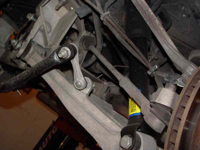
Re-install the lower control arm nuts onto the bolts for safe-keeping and to keep the bolts from sliding out. Examine the upper left corner of Fig
1 and you will see the sway bar mounting bolt on top and the lower control arm pivot bolt and nut just below it. Note that on this car there were several washers
on the lower control arm pivot bolt / sway bar mount. These were to adjust for a non-factory catback system and are not found on most C5's. (Fig. 1)
Remove the two muffler/over axle pipe assemblies (the catback system) and place out of the way of your work.
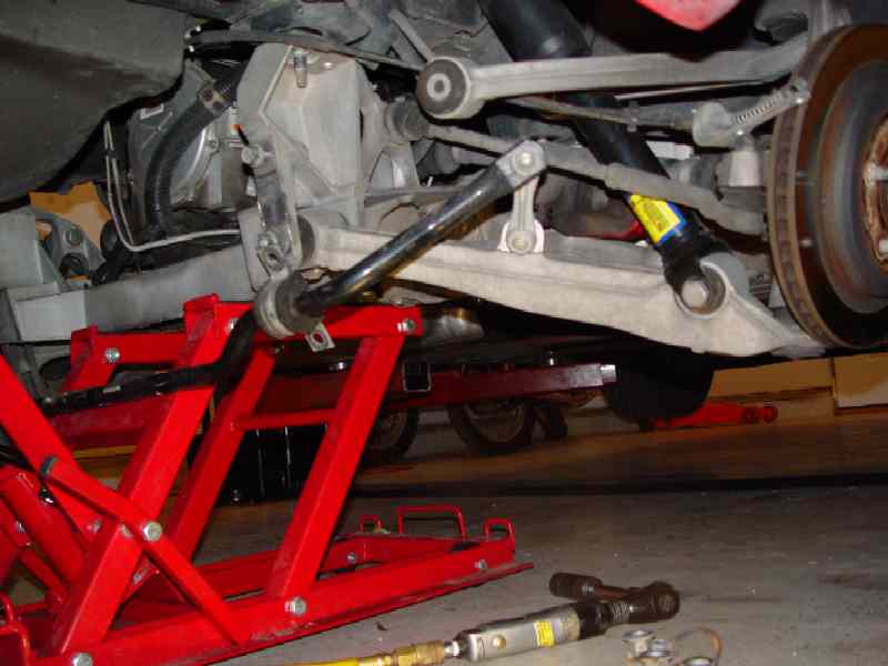
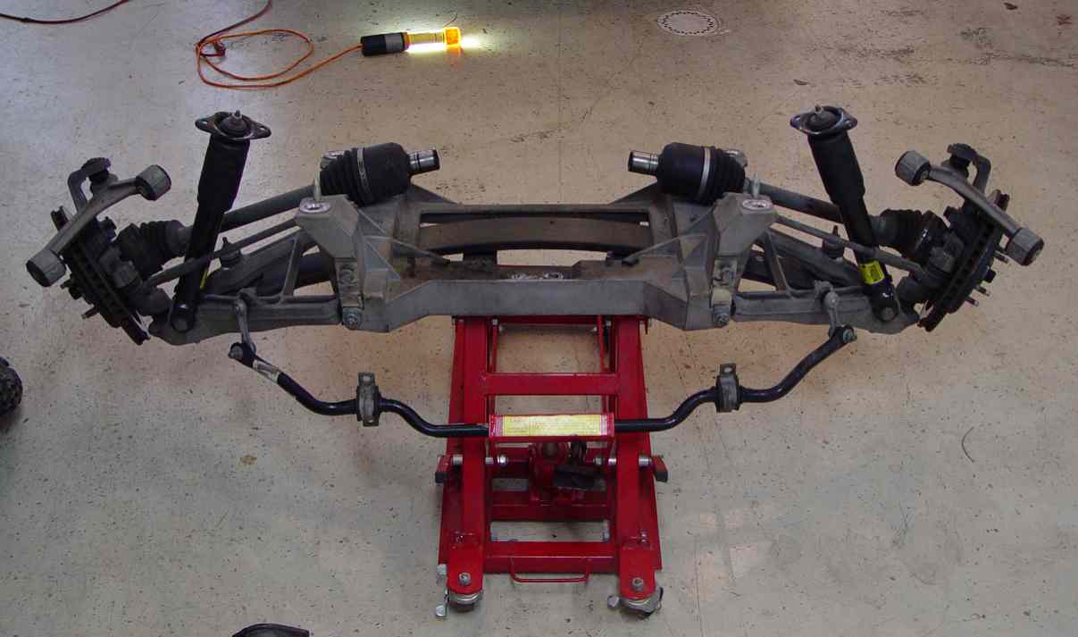
You are going to remove the whole aluminum suspension cradle, shocks, upper and lower control arms, halfshafts and rotors as a complete assembly.
Position a motorcycle/atv jack or appropriate support under the center of the rear suspension cradle. (Fig. 2)
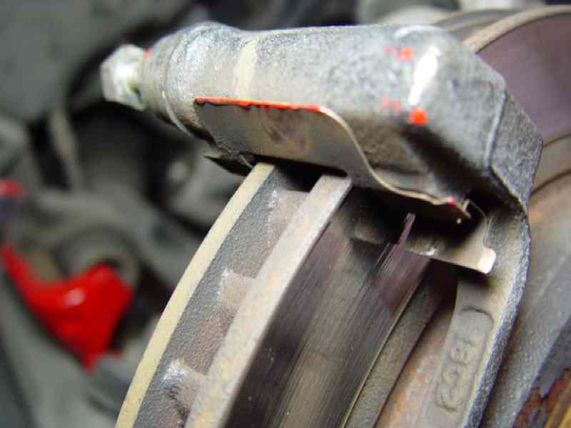
Remove the 4 (2 each side) caliper mounting bolts and pull calipers free. Label and set aside.
Use some coat hanger wire to fashion hangers to support the brake calipers to avoid damaging the brake lines.
Gather the brake pads and retainer clips and put them in a safe place until needed for re-assembly.(Fig. 3)
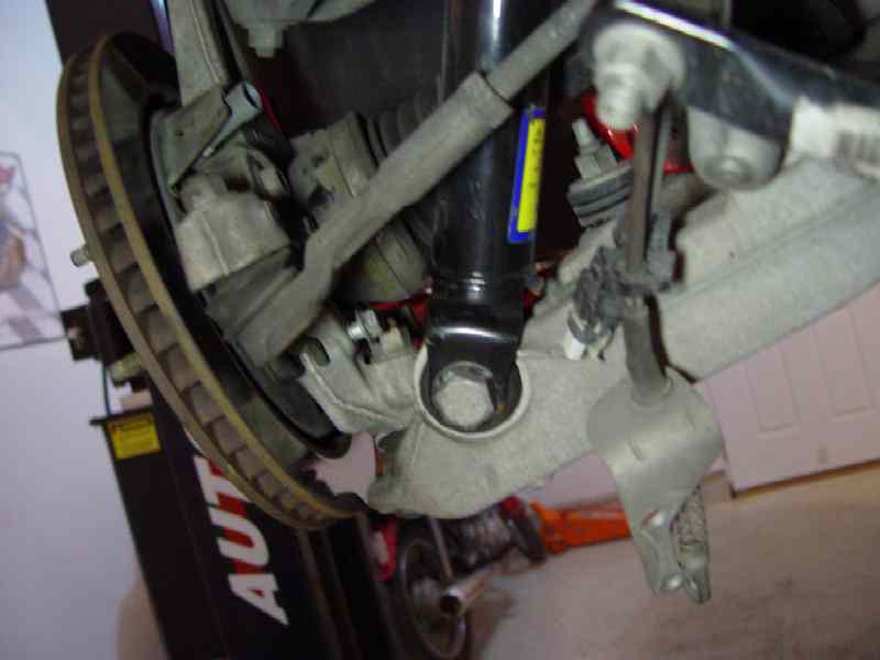
Locate the emergency brake cable ends and pull them from the emergency brake actuator levers (one on each side).
You should be able to remove these with just your hands. If not, use a pair of pliers and pull the hoop on the cable-end
down and off of the brake actuator lever.(Fig. 4)
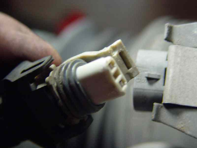
Disconect the two (one on each side) wheel speed sensor wires. (Fig.5)
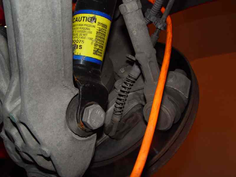
Remove the emergency brake cable bracket by removing the two 15mm bolts that hold it on. You will not be able to remove the lower bolt
fully until the upper control arm is detached from the chassis, as the lower shock is in the way.(Fig. 6)
If the car is equipped with the F45 adjustable suspension, there are two 8mm heim link bolts that screw into the forward arm of
the upper control arms (one on each side - visible in Fig. 7). Remove them from the control arm and let them dangle. The fasteners will stay attached to the position sensor on the F45 unit.
There are two wires that are gathered and routed over the top of the F45 position sensor unit (Fig. 7). Locate the connector
sockets and disconnect the smaller of the two. Unclip the 4 (two on each side) gathering ties on the top of the F45 unit and let the wire hang down.
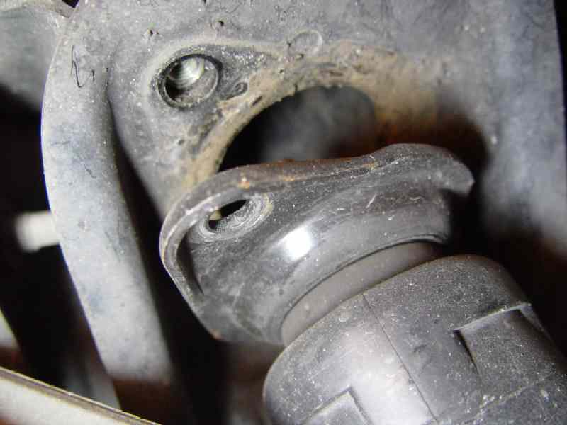
Remove the two 13mm bolts on the upper shock mounts. Label and set aside. (Fig. 8)
Remove the 4 (two each side) upper control arm pivot bolts (18mm hex head). Label and set aside. (Fig. 9)
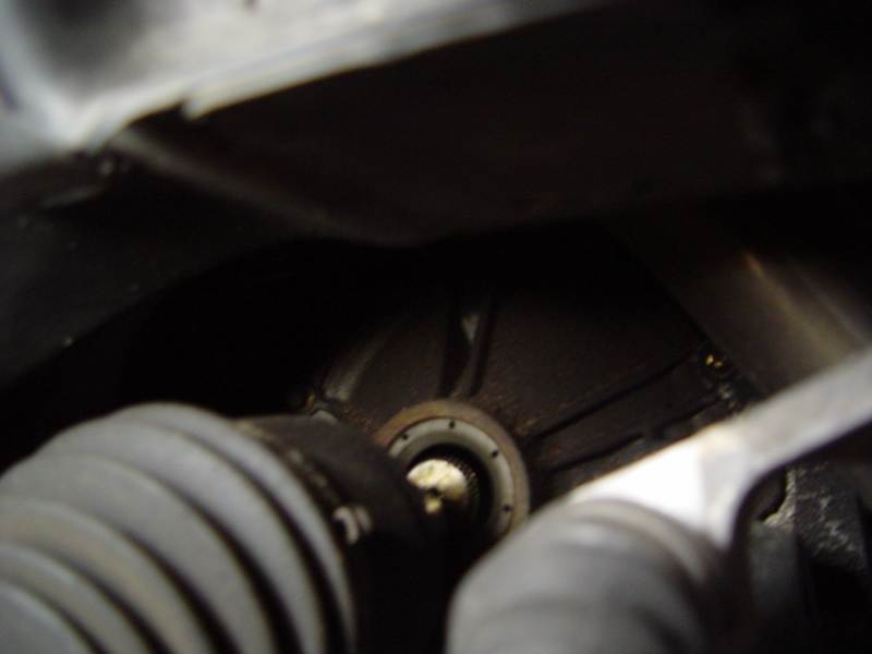
Once the upper control arms and top shocks mounts are detached, you can pry the halfshafts out of the
differential. I used a long tire iron that I use for changing dirt bike tires.
It seemed that the drivers side halfshaft was harder to pop out of the diff.
Just pry the half-shafts out of the diff if you cannot pull them out.
(Fig. 10)
Examine the electrical harness that runs down from the top of the differential on the passenger side and across the suspension cradle.
You will find a three plastic retainer loops that hold the harness to the cradle. Pop them apart with a screwdriver and pull the electric harness free.
(Fig. 11)
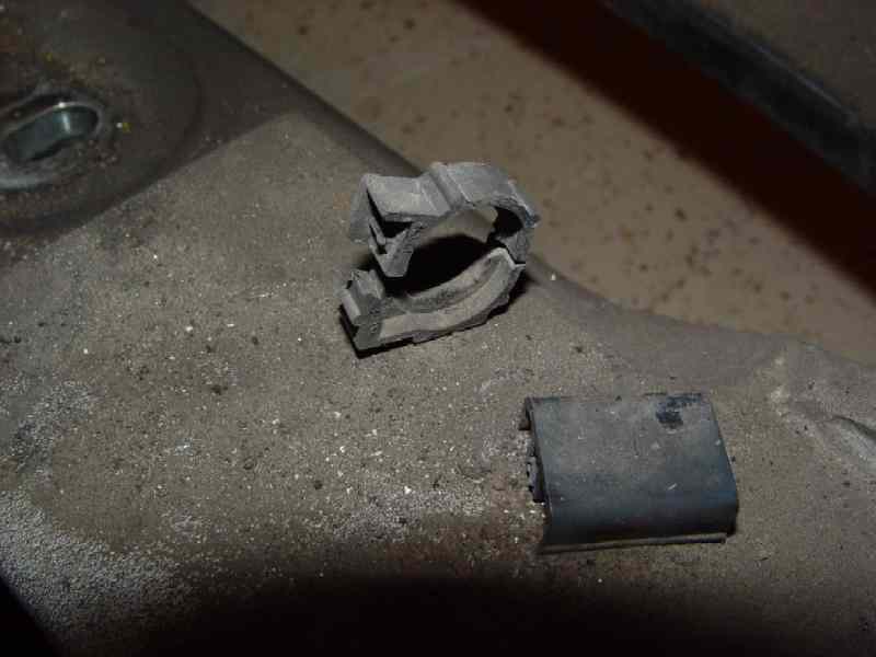
Examine the brake lines and how they route and are retained along the suspension cradle. There are 4 black
plastic push-in retainers that hold the lines to the suspension cradle. Push or pry the brake line retainers up
and out to allow the brake lines to separate from the suspension cradle. (Fig. 12 and 13)
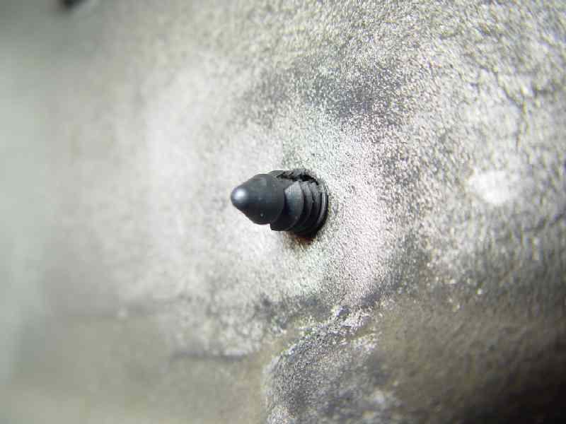
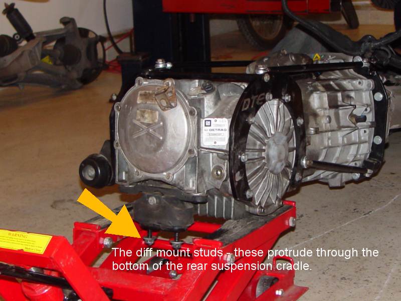
Remove the two 13mm nuts from the studs on the differential mount. The studs protrude down through holes in the suspension cradle. (Fig. 14)
Once the brake lines, electrical harness, upper shock mounts, upper control arm pivots and the brake calipers are free, you can lower the cradle.
Carefully examine the suspension cradle - re-check to ensure all of the attachment points are free.
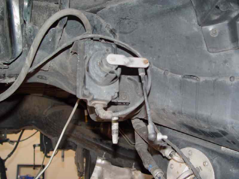
Place a floor jack or suitable support under the transmission at the transmission to torque-tube mounting location.
Loosen the four (two on each side) 21mm nuts that hold the suspension cradle to the chassis. Use the jack
to allow the cradle to lower down and away from the chassis. (Fig. 15)
*Note* GM insists that these four nuts be replaced
and not re-used.
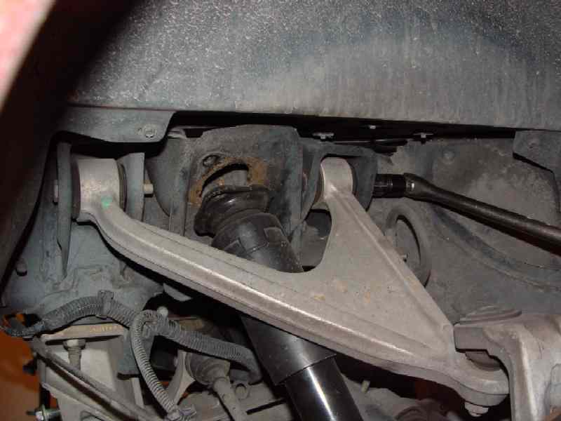
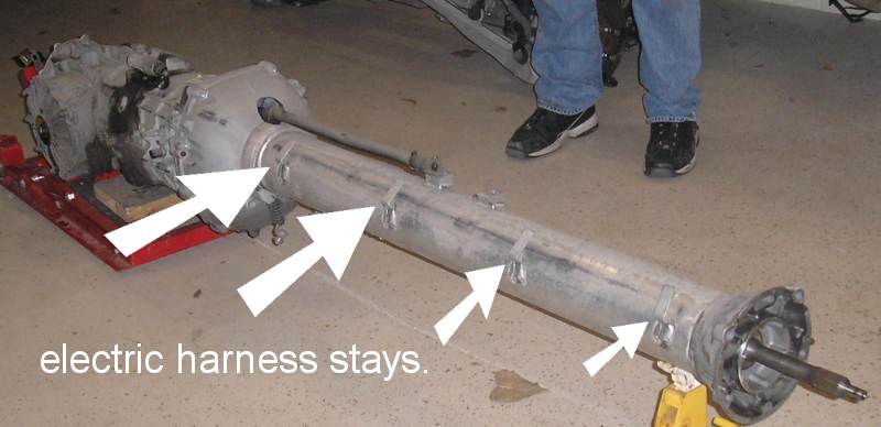
The main electric harness is routed along the torque-tube on the passenger side. The torque tube has large brackets, or stays (Fig. 16), that the harness
slips down into. You can push the harness up and out of the stays so that the torque tube is free to be removed.
Roll the cradle out and to the rear while making sure the wiring harness and brake lines all stay in place.
Remove the suspension cradle from the atv lift - two fellows can manage it - and set the cradle out of the way.
Position the ATV lift under the diff/transmission.
Remove the electrical connectors from the transmission. There is a vehicle speed sensor wire,
the CAGS solenoid wire, the reverse lockout wire, and if the car is a Z06,
the transmission temperature sensor. Disconnect all the connectors.
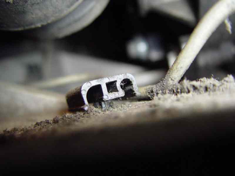
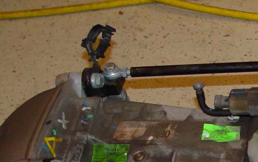
On the transmission to torque-tube mounting location, on the upper passenger side, there is a metal
bracket that holds a plastic electric harness retainer loop. Pry the plastic retainer loop open to release
the wiring harness. (Fig. 17)
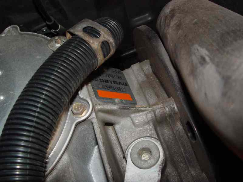
On the rear differential case, on the upper passenger side, there is a metal electrical harness retainer loop.
Pop it open with a screwdriver and pull the harness free. (Fig. 18)
The driveline is now only attached by the 5 13mm torque-tube to bellhousing bolts. Remove those bolts and pull the driveline free,
being careful not to snag the brake lines at the rear of the diff, the electric harness that runs along the torque-tube, or the lower rear fascia.